


Earn {{points}} for every {{amount}} you spend and turn them into discounts at checkout.
Join now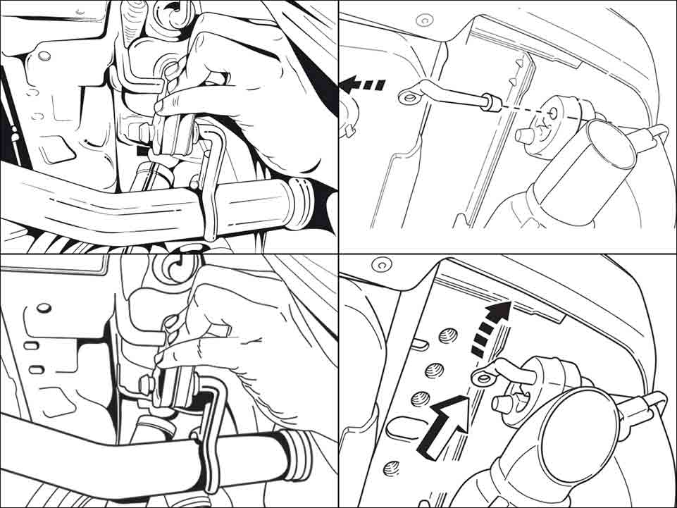


Why Choose Maa Illustrations
Excellent Trustpilot Rating
100% Unique Illustrations
Money Back Guarantee
Secure Payment by Shopify
Unlimited Art Work Revisions
You’ll Own All Copyrights
Other Technical Illustration Service
Transform Your Space with Our Technical Illustration Collection
Professional Architectural Technical Drawing Se...
£10.00
Transform Your Vision with Our Professional Architectural Technical Drawing ServicesWhen it comes to realizing your architectural dreams, professional architectural technical drawing services are essential. At Maa Illustration, we specialize in crafting detailed and precise illustrations of your architectural designs. Whether you're an architect, designer, or homeowner, our expert illustrators generate accurate floor plans and elevations that enhance visualization and facilitate effective communication with stakeholders.Imagine having each aspect of your project clearly depicted, allowing you to make informed decisions and streamline your project workflow. Our illustrations not only save you time but also help convey your ideas more efficiently, ensuring everyone is on the same page.
Precision-driven architectural drawings tailored to your specifications
Quick turnaround times without compromising quality
Competitive pricing with unmatched value for your investment
Guaranteed satisfaction—your vision is our priority!
Special pricing available for orders of ten illustrations or more
Don’t leave your project’s success to chance. Trust our experienced team for exceptional architectural drawings that bring your ideas to life. Ready to get started? Get a free illustration quote today and discover how we can help you transform your architectural concepts into stunning visual realities!

Expert Archaeological Illustrations - Bring His...
£10.00
Expert Archaeological Illustrations: Transforming History into Stunning Visuals Unlock the past with our Expert Archaeological Illustrations that bring history to life like never before. Whether you're an academic, museum curator, or simply passionate about archaeology, our custom artwork enhances your projects and engages your audience deeply. At MAA Illustration, we understand the importance of accuracy and detail in illustrating archaeological finds. Our team of skilled artists specializes in creating lifelike representations of ancient artifacts and historical sites, tailored to your specific needs. With our illustrations, your findings gain a new dimension, making it easier for your audience to connect with the stories behind the images. Fast delivery to meet tight deadlines. Competitive pricing, ensuring value for your investment. Unlimited revisions to ensure your complete satisfaction. Customizable illustrations to fit educational, museum, and research purposes. Special pricing available for orders exceeding ten illustrations. Don’t let your archaeological findings gather dust! Let our Expert Archaeological Illustrations enhance your presentations and publications. Get a free illustration quote today!
Professional Technical Line Drawings to Elevate...
£10.00
Transform Your Projects with Professional Technical Line Drawings Are you looking for Professional Technical Line Drawings that can elevate your projects and effectively communicate complex ideas? Look no further than Maa Illustration! Our expert team specializes in creating precise and detailed line drawings tailored for various industries, including engineering, architecture, and manufacturing. Our technical illustrations not only clarify your concepts but also enhance your presentations, proposals, and technical documents. With our work, you can foster better understanding among stakeholders, clients, and team members, making your projects stand out. Accurate and comprehensive line drawings to capture intricate details Custom designs for architectural, engineering, and manufacturing needs Fast turnaround time to meet tight deadlines Special pricing available for orders over ten illustrations Free quote to ensure you stay within your budget By choosing Maa Illustration, you're investing in quality and clarity for your technical projects. Don't let your ideas get lost in translation—contact us today for a free illustration quote and see how our Professional Technical Line Drawings can make a difference in your work! Get a free illustration quote
Professional Technical Illustrations for Enhanc...
£10.00
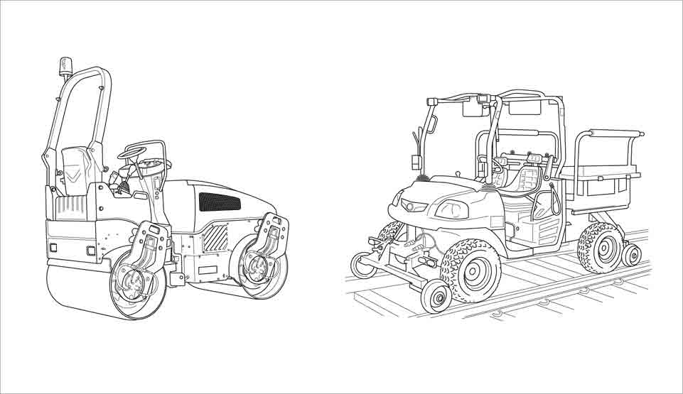
Elevate Your Product Presentations with Professional Technical Illustrations Transform your product presentations into powerful storytelling tools with our Professional Technical Illustrations. We specialize in creating intricate and accurate illustrations tailored specifically for industries such as engineering, manufacturing, and marketing. Our goal is to help you showcase your products in a visually compelling manner that resonates with your audience. By choosing our technical illustrations, you not only improve the visual appeal of your documentation, but you also ensure that your products are presented with clarity and precision. This can significantly enhance customer understanding and engagement, leading to improved sales.
High-quality illustrations: Crafted with attention to detail, suitable for various product types.
Quick delivery: We understand the urgency of your projects and deliver on time.
Affordable pricing: Competitive rates without compromising quality.
Custom solutions: Contact us for special pricing on orders over ten illustrations. Whether you're preparing a marketing campaign or technical documentation, our illustrations can make all the difference. Get a free illustration quote today and take the first step towards enhancing your product presentation!
Professional Photo Tracing Services for Accurat...
£10.00
Unlock Precision with Our Professional Photo Tracing Services
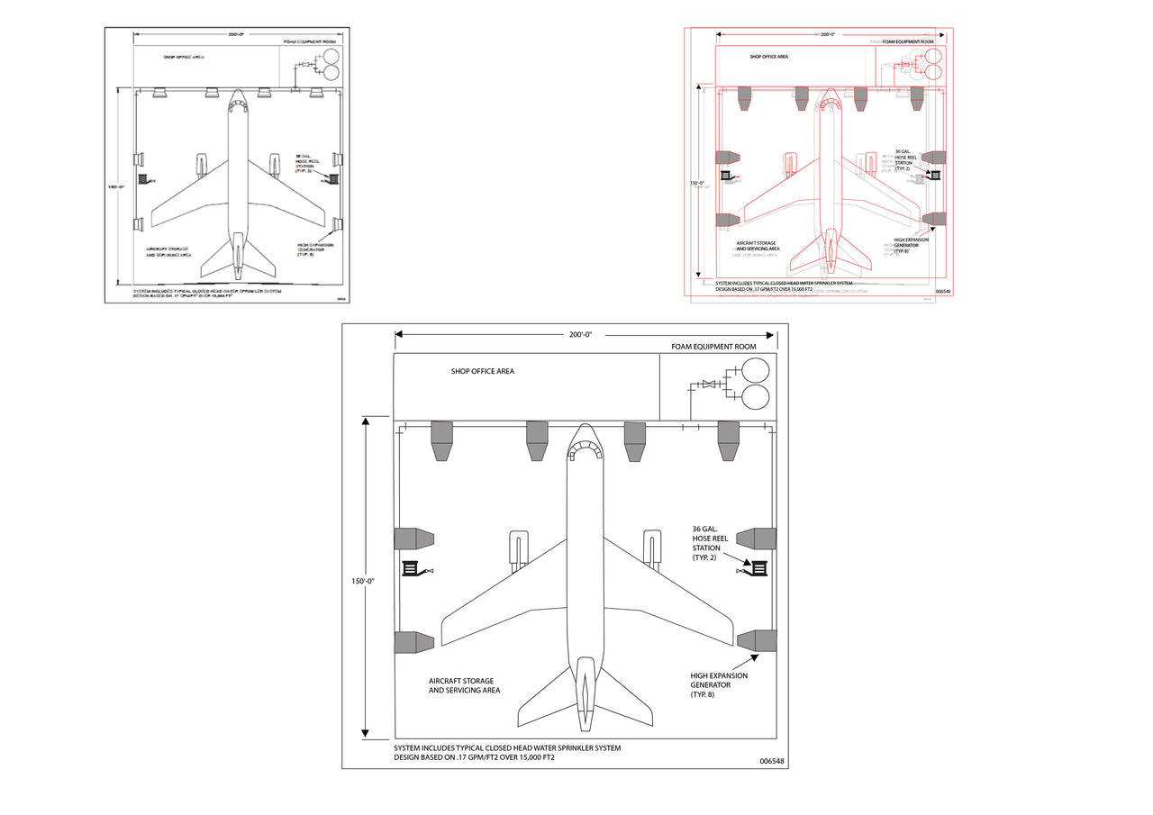
Elevate your design projects with our Professional Photo Tracing Services, designed to create precise technical drawings that breathe life into your concepts. We understand how crucial accuracy is in fields like engineering, manufacturing, and architecture. Our team focuses on meticulous detailing to ensure that every trace reflects the exact specifications you need.
By choosing our photo tracing services, you're not just outsourcing work; you're investing in quality that enhances your business credibility. Quick turnaround times and affordable rates help you stay on schedule without breaking the bank. Plus, our promise of satisfaction guarantees that you’ll receive high-quality results every time.
Expert tracing for objects, structures, and machinery
Tailored solutions for engineering, manufacturing & architecture
Competitive pricing with great value
Fast delivery to meet pressing deadlines
Special pricing available for bulk orders over ten illustrations
Why settle for less when you can have precision, reliability, and affordability all in one service? Contact us today to get a free quote and bring your ideas to life with our Professional Photo Tracing Services. With our dedication to excellence, your satisfaction is our top priority!
Get a free illustration quote
Professional Technical Illustration Services fo...
£10.00
Transform Your Data with Expert Technical Illustration Services
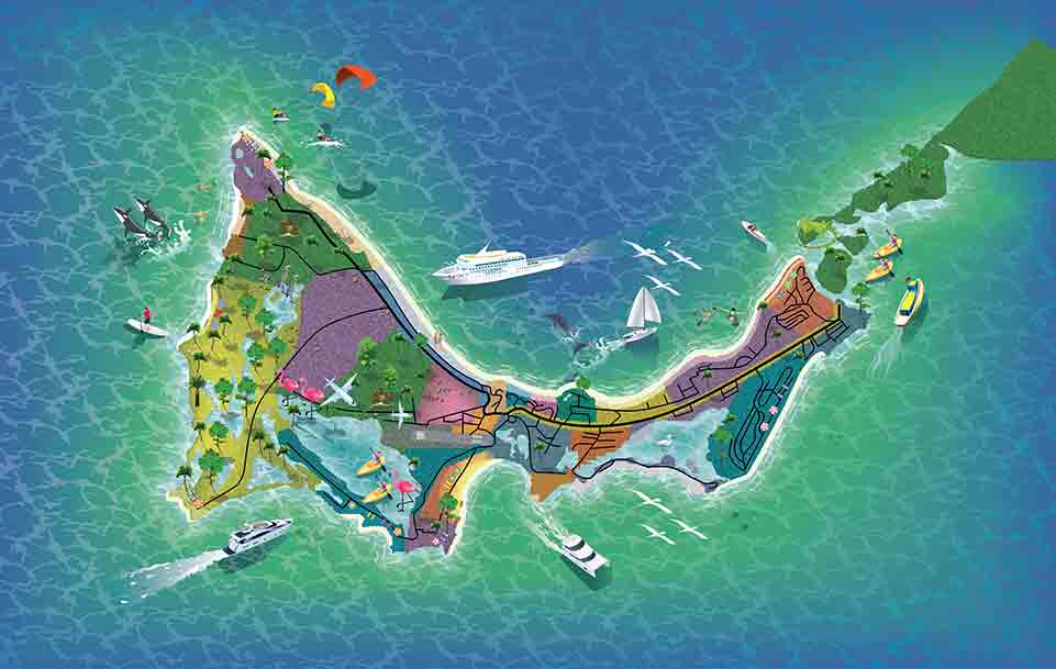
Are you struggling to present complex data in a way that captivates your audience? Our technical illustration services are designed to simplify that challenge. At Maa Illustration, we specialize in creating precise and visually engaging charts that make your data easy to understand and more accessible. Whether you're in engineering, manufacturing, or architecture, our illustrations provide clarity and enhance comprehension.
Imagine your intricate graphs and charts transformed into professional visuals that communicate exactly what you want them to. Our experienced team ensures fast delivery, cost-effective solutions, and remarkable quality. Let us turn your complex data into powerful visuals that resonate with your audience and enhance presentations.
Fast turnaround time for all illustration requests.
Competitive pricing tailored to fit your budget.
Expert illustrators with a keen eye for detail.
Custom illustrations tailored to your specifications.
Perfect for engineering, architecture, and manufacturing needs.
If your project requires more than ten illustrations, don't hesitate to contact us for a special pricing package. We want to ensure you get the best value for your needs.
Ready to elevate your data representation? Get a free illustration quote today!
Hire a Fashion Illustrator for Stunning Fashion...
£10.00
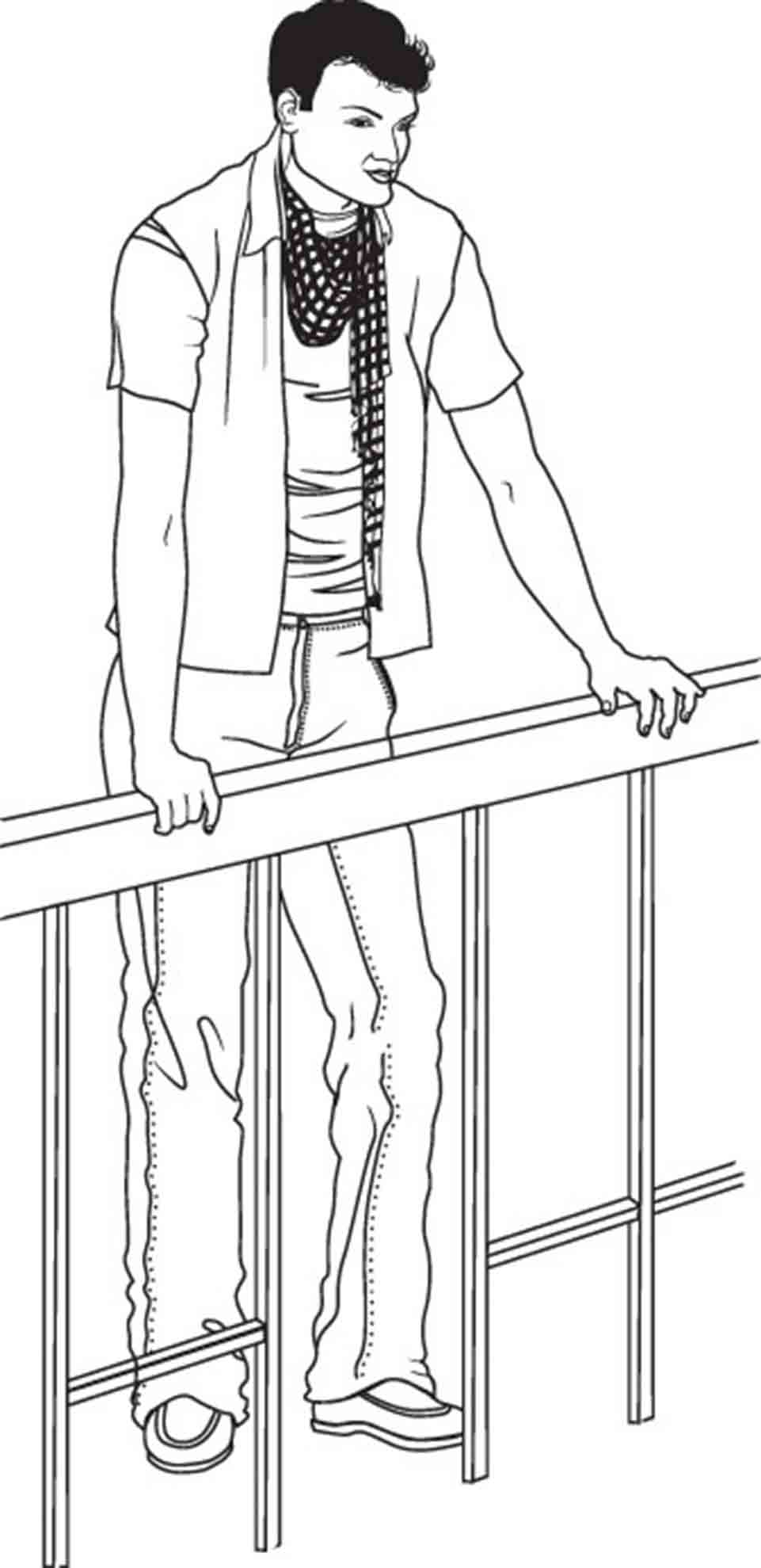
Hire a Fashion Illustrator: Transform Your Design Concepts into Stunning VisualsWhen you hire a fashion illustrator, you gain the ability to effortlessly bring your creative ideas to life. Our exceptional fashion and flat drawings are designed to help fashion designers like you visualize and communicate your design concepts with clarity and style. Instead of struggling to sketch your vision, let our talented illustrators craft exquisite artwork that elevates your portfolio.Imagine showcasing your designs with professional and visually stunning artwork that captivates your audience. Our fast delivery and competitive pricing ensure that you can focus on your creativity while we handle the visual storytelling.Key Highlights:
Exceptional quality illustrations tailored to your unique style
Quick turnaround to meet your project deadlines
Competitive pricing options to suit every budget
Unlimited revisions until you're completely satisfied
Special pricing available for over ten illustrations
Don’t let your ideas remain on paper! Let our experienced illustrators add that professional touch to your fashion portfolio. Get a free illustration quote today and unlock the full potential of your fashion designs!
Professional Assembly Instruction Illustrations...
£10.00
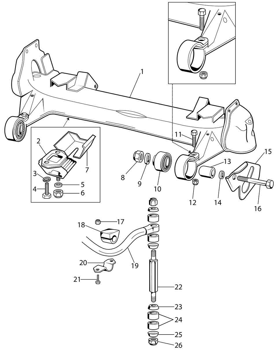
Elevate Your Assembly Experience with Professional Assembly Instruction Illustrations
Our professional assembly instruction illustrations are designed to enhance user understanding, simplifying the installation process for consumers and professionals alike. At MAA Illustration, we provide technical illustrations that not only offer precise visual guides but also significantly improve the user experience.
Imagine eliminating confusion and frustration during assembly tasks. With our expertly crafted illustrations, users will find it easy to follow instructions, ensuring that installations are completed smoothly and efficiently.
Quick turnaround time for all illustration requests
Competitive pricing without compromising quality
Guaranteed satisfaction with every project
Ideal for consumer goods and industrial equipment
Custom quotes available for bulk illustration orders
Don't let complicated assembly instructions hold you back. Upgrade your manual with our professional illustrations and see the difference in user satisfaction. For orders over ten illustrations, contact us to receive a special price tailored just for you!
Get a free illustration quote
Custom Technical Illustrations for Manuals: Enh...
£10.00
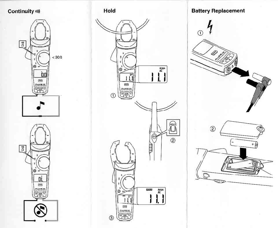
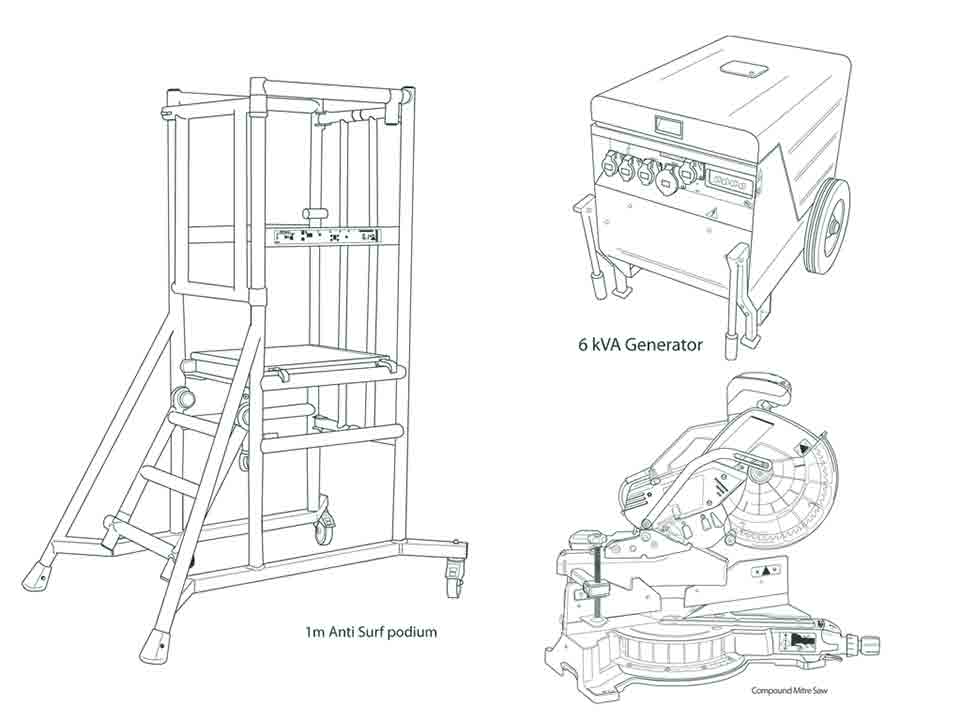
Transform Your Manuals with Custom Technical Illustrations for ManualsSay goodbye to confusion and hello to clarity with our custom technical illustrations for manuals. MAA Illustration is dedicated to enhancing the user experience by creating stunning, easy-to-understand visuals tailored specifically for your technical documents. Whether it's an assembly guide or a user manual, our illustrations will make intricate details simpler to grasp.With a clear focus on effective communication, we ensure your manuals not only look professional but also significantly improve understanding—boosting user satisfaction and reducing support inquiries. Fast delivery and competitive pricing make it easier than ever to elevate your manual's quality. Focus on your product while we handle the visuals!
Custom illustrations designed to meet your specific manual requirements
Quick turnaround times to align with your project deadlines
Affordable pricing to accommodate any order size
High-quality visuals that instill confidence in your customers
Exclusive discounts for bulk orders of ten or more illustrations
Don’t let unclear instructions tarnish your product’s reputation. Elevate your manuals with our professional illustrations today! Get a free illustration quote and witness the transformative power of our custom technical illustrations!
Professional Piping and Instrument Drawings | H...
£10.00
Transform Your Projects with Expert Piping and Instrument Drawings
When it comes to Piping and Instrument Drawings (P&ID), precision and clarity are essential for your projects' success. At Maa Illustration, we specialize in providing high-quality, detailed diagrams that elevate your engineering projects and streamline communication within your team. By outsourcing your P&ID needs to our skilled illustrators, you ensure accuracy and professional quality that meets industry standards.
Our expert illustrators are trained to deliver exceptional results that not only comply with the requirements of various sectors, such as chemical, petrochemical, and oil and gas industries but also enhance your overall productivity. Here’s how our service can improve your work life:
Fast Turnaround: We understand deadlines are crucial. Count on us for quick delivery without compromising on quality.
Competitive Pricing: Get exceptional illustrations at better prices. Contact us for special rates on orders of ten or more diagrams!
Guaranteed Satisfaction: Your satisfaction is our priority. We don’t stop until you’re completely happy with the work.
So whether you need to create brand-new P&IDs or redraw existing ones, we’re here to help. Take the stress out of your technical illustration needs and focus on what you do best. Get a free illustration quote today and discover how our professional piping and instrument drawings can make a difference in your projects.
Custom Technical Illustrations: Engaging Pictog...
£10.00
Transform Your Projects with Custom Technical Illustrations
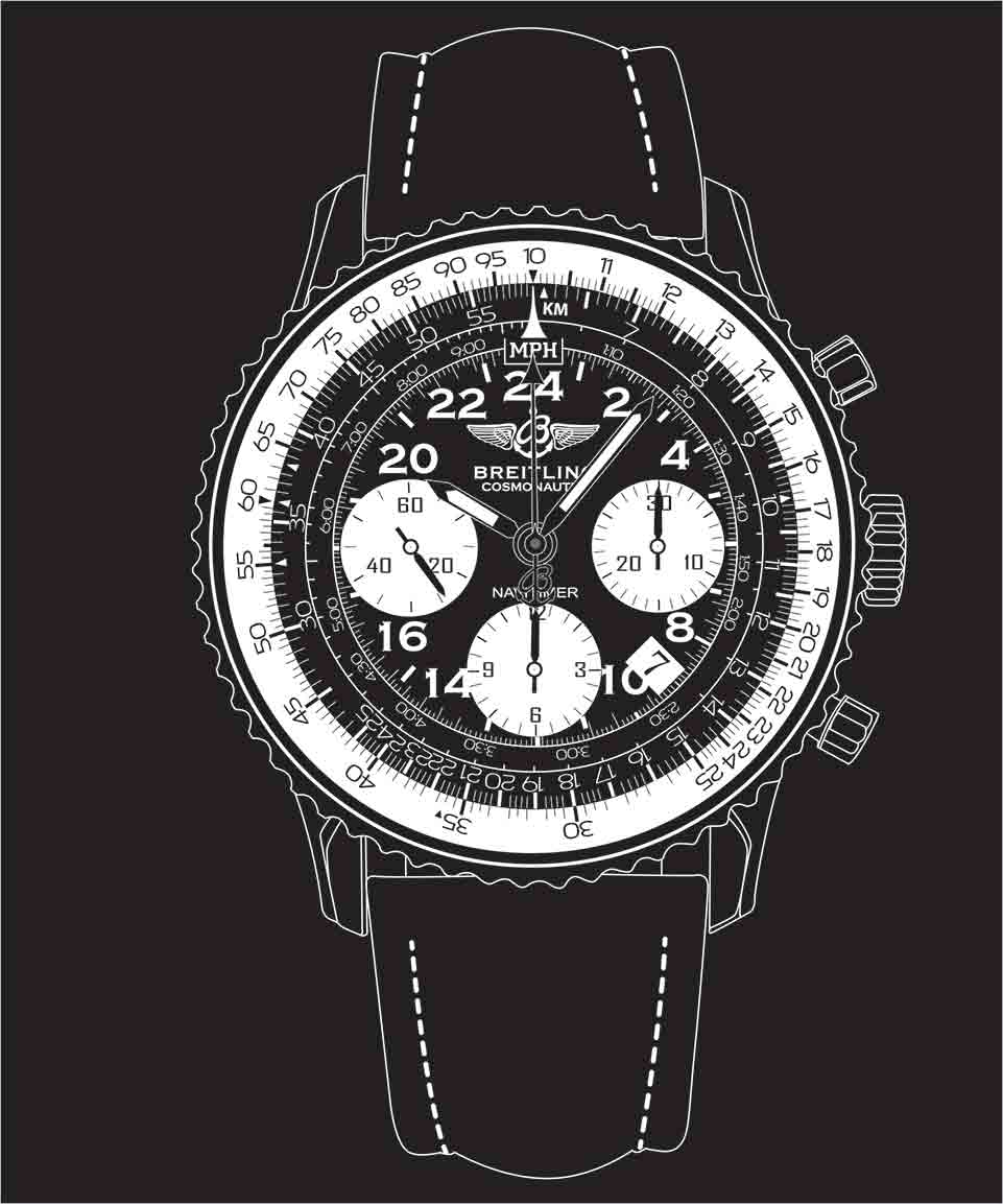
Unlock the potential of your projects with our Custom Technical Illustrations. At Maa Illustration, we understand that clear communication is vital, especially when it comes to technical documentation. Our engaging pictograms and icons are designed to simplify complex information, making it easy for your audience to understand your message.
Whether you’re developing a catalogue, manual, or any instructional material, our illustrations are tailored to enhance the user experience. Visually appealing and informative, our icons work seamlessly across logos, websites, apps, and branding initiatives. You’ll not only save time trying to create visuals from scratch, but you’ll also enjoy fast delivery and competitive pricing.
High-quality, unique pictograms and icons
Perfect for catalogues, manuals, and instructional materials
Boosts engagement and understanding for your audience
Quick turnaround times and satisfaction guaranteed
Special pricing available for bulk orders of more than ten illustrations
Don't let your message get lost in translation. Elevate your branding and instructional content with our Custom Technical Illustrations today! Get a free illustration quote to see how we can make your visuals stand out.
Unleash the Power of Exploded Technical Illustr...
£10.00
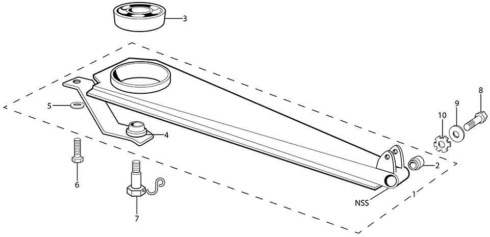
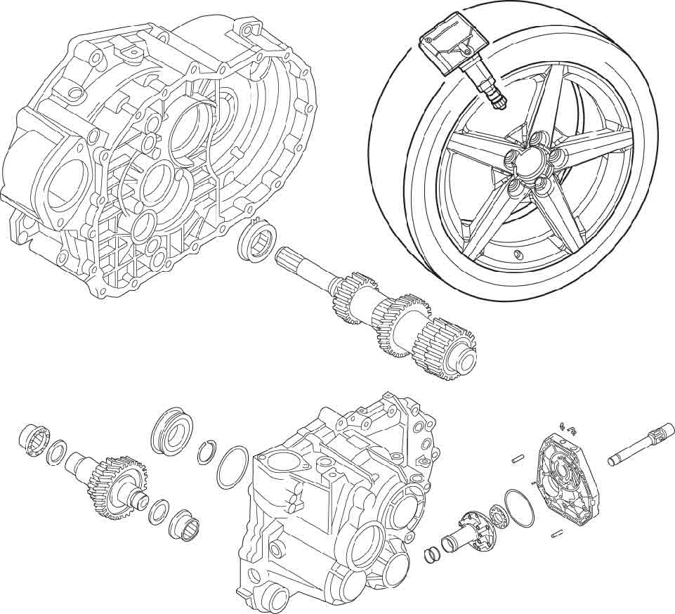
Transform Your Projects with Our Exploded Technical Illustration ServicesUnleash the power of our exploded technical illustration services and elevate your visual communication to new heights. We understand that clear and detailed visuals can make all the difference in how your audiences grasp complex concepts. With our expert team, you can expect tailor-made illustrations that enhance your technical manuals, assembly instructions, marketing materials, and much more.Imagine delivering your projects with stunning visuals that not only inform but also engage your audience. Our fast delivery and competitive pricing mean you can focus on what truly matters—your content. Plus, we guarantee your satisfaction, ensuring you receive exceptional illustrations that meet your specific needs.
High-quality, custom illustrations for various applications.
Quick turnaround time to keep your projects on track.
Competitive pricing tailored for any budget.
Unlimited revisions until you're completely satisfied.
If you need more than ten illustrations, don’t hesitate to contact us for a special price. Our team is ready to help you create outstanding visuals that draw in your audience!Get a free illustration quote
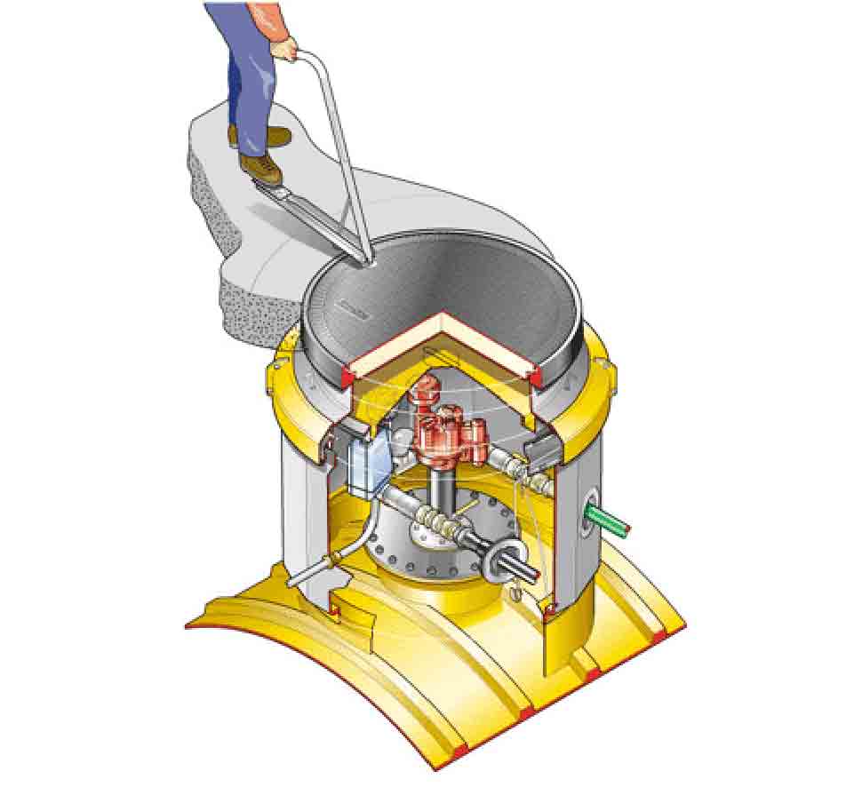
Custom Cutaway Illustrations Services – Bring Y...
£10.00
Unleash Creativity with Custom Cutaway Illustrations ServicesElevate your designs and captivate your audience with our custom cutaway illustrations services at Maa Illustration. Imagine transforming intricate concepts into visually stunning representations, allowing your clients to see not just the surface but the detailed inner workings of your projects. Whether you’re in engineering, architecture, or product design, our expert illustrations simplify complexity and enhance understanding.By choosing our services, you empower your projects with not only breathtaking visuals but also the confidence of timely delivery and competitive pricing. Each illustration is crafted to reflect your unique vision, ensuring a perfect alignment with your goals.
Meticulous attention to detail for true-to-life depictions
Rapid turnaround times that keep your projects on deadline
Budget-friendly options, with additional savings on bulk orders
100% satisfaction guarantee from our dedicated professional team
Are you ready to bring your ideas to life? Click below to receive your free illustration quote and discover how our custom cutaway illustrations services can revolutionize your projects! Get a free illustration quote

Professional Technical Illustration Services | ...
£10.00
Transform Your Visuals with Our Professional Technical Illustration ServicesElevate your projects and enhance understanding with our Professional Technical Illustration Services. In a world where clarity is key, our expert team revitalizes your outdated technical illustrations through precise redrawing and retracing techniques. With our digitising and vector tracing methods, every detail comes to life, ensuring your visuals are not only accurate but also captivating.Imagine transforming outdated drawings into modern, crisp visuals that can be easily scaled and modified to suit your needs. Our quick delivery and unlimited revisions guarantee your satisfaction, giving you peace of mind as you invest in quality.
High-Quality Results: Crisp, clear, and professional illustrations tailored to your specifications.
Scalable and Modifiable: Easily adjust your illustrations to fit various applications.
Unlimited Revisions: Your satisfaction is our priority; make changes until you're thrilled with the result.
Fast Turnaround: Get your updated illustrations quickly without compromising quality.
If you require more than ten illustrations, reach out to us for a special pricing option. Don’t let outdated visuals hold you back—get a free illustration quote today and take the first step toward stunning technical drawings!